1. Power Requirements and Business Internet
- Internet Router
- Local Cloud (Black Box)
- Internal WiFi Access Point POE
- External WiFi Access Point POE
Home run the Ethernet cables:
WiFi Access Points use POE or Power-over-Ethernet adaptors to provide connectivity and power. We recommend “home-running” all the Ethernet cables to near the router to ensure the POE adapters are connected to the battery backup.
Printers: No battery backup needed and use WiFi not Ethernet cables.
Printers need standard 110V power, but do not require battery backup. Printers pop the cash drawer but in case of power failure or the rare event of printer failure, the cash drawer can be opened manually with the included key.
Internet: Business Internet is required
ISPs tend to notice that a local cloud is installed, and will often block access to the Internet unless you subscribe to “business internet.” This is usually accomplished with a simple phone call to your ISP.
2. Recommended Wifi Access Point Install Location
WiFi operates approximately in line-of-sight. Choose the most suitable location.
External Wifi Access Point (optional):
Choose an external location where you can see the Access Point from the areas you want coverage.
Internal WiFi Access Point should be centrally located:
Mount internal WiFi in ceiling.
Be aware that freezer will block signal.

For longevity of external Access Points, use "shielded outdoor ethernet cable" (Cat 5e or Cat 6) with an ESD drain wire.
Double or Dual PVC Jacket will provide additional longevity of the cabling, especially when not using conduit. Other keywords include “outdoor carrier class shielded Ethernet cable with double PVC jacket, foil shielding and ESD drain wire.”
3. Hardware installation, verification, troubleshooting
You want to make sure your staff knows the Touchpoint components.
If you have opted for the setup with 4G Cell Backup, please scroll down do

3.2 Add 4G Failover3.1 Original Setup
The networking equipment is pre-configured. It only needs to be connected correctly, according to the following diagrams.
3.1.1 Installation & Understanding Components
Connect all Touchpoint components to a battery backup!

- Internet Router (ISP) connects to WAN Port of Local Cloud
- Local Cloud LAN port to LAN port on Power Adaptor
- POE port on Power Adaptor to MAIN port on Internal Wifi Access Point
- Secondary port on Internal Wifi to LAN on Power Adaptor. (NOTE: Verify labels)
- POE on Power Adaptor to Main on External WiFi Access Point
Tip: Home Run all the Ethernet cables for POEs to be near battery backup
Please take a moment to verify that the following conditions are true.


Turning Local Cloud On/Off
Note: Do not turn off the Local Cloud unless Touchpoint staff instructs to do so!
Here is how to correctly turn off the local cloud:
1. To turn off Touchpoint Local Cloud, press and release the button. The green power led on the Local Cloud should turn off within 20 seconds.
2. When it's turned off, unplug the power cord, wait 10 seconds and plug it in again.
3. Press and release the power button. The Local Cloud should now turn on again.
It can take a couple of minutes for the system to boot. Then you will be able to connect your iPads again.
Power Cycling WiFi Access points
Find the (black/white) POE and unplug it from the power source. Make sure the blue ring/power led on the Access Point and power led on the POE are out.
Now re-plug the power cord.
Internal Access Point - POE

External Access Point - POE

3.2 Add 4G Failover (optional)
3.2.1 Installation & Understanding Components
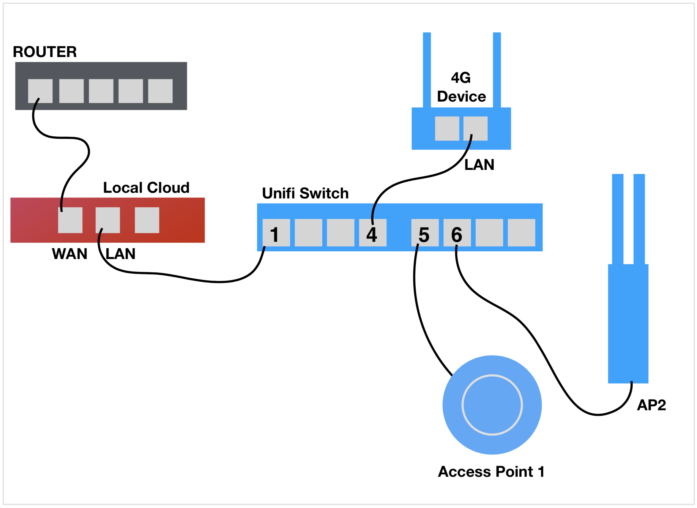
In the original setup, WiFi Access Points (AP's) used POE connectors. With the switch, these POE adaptors are no longer necessary. The AP's can be connected directly to specific ports on the Ubiquity POE switch.
Only Ports 5, 6, 7, 8 will power the AP's!

Installation Steps:
1) Plug in Unifii Switch to AC Power.
2) Connect Port 1 of the switch to LAN on the Touchpoint Local Cloud
3) Connect Port 4 of the switch to LAN on the 4G device
4) Connect Port 5 of the switch to Main port of UFO Access Point
5) Connect Port 6 of the switch to Bunny Ears External AP (if present)
Configure Exactly
Plug in the Touchpoint components exactly as specified

Next, perform the verification steps
3.2.2 Verification and Troubleshooting steps


If you follow these instructions and are still facing issues, please call 1-800-992-9540 to schedule a time to receive set-up support.
3.2.3 4G Failover Device Indicators
Please allow that it may take 3 to 5 minutes to make the initial connection to the Internet and illuminate the Globe. If you do not see the Globe indicator glowing green, please re-position your device, power cycle and wait 3-5 minutes.

4G wireless connectivity is provided by T-Mobile. If you do not have adequate coverage in your location, 4G failover won’t work in your store. Contact Touchpoint support as we are investigating options with AT&T if you source the SIM yourself. Note that this device is not compatible with Verizon, Sprint or other wireless providers.
3.3 Triple Access Point Setup
3.3.1 Installation & Understanding Components
NOTE: In the original setup, WiFi Access Points (AP’s) used POE connectors. With the switch, these POE adaptors are no longer necessary. The AP’s can be connected directly to specific ports on the Ubiquity POE switch. Only Ports 5,6,7,8 will power the AP’s

Installation Setup:
1) Plug in Unifii Switch.
2) Connect Port 1 of the switch to LAN on the Touchpoint Local Cloud
3) Connect the UFO Internal Main AP to Port 6
4) Connect the Bunny Ears External AP to Port 7
5) Connect the Bunny Ears External AP to Port 8
Next, perform the verification steps on the following page.
3.3.2 Verification and Troubleshooting steps
1) Please take a moment to ensure all cables are plugged in accurately. After a few minutes, the Unifi Switch will Power should glow Blue.


